5 minutes
How to change display resolution in hardware
Disclaimer
Don’t try this at home or you may break your device.
Story
I recently had an odd problem with an old Dell monitor (U2711). I’ve fixed this issue numerous times before in software, but I got tired of having to do it all the time. What was the issue? Well the display supports 1440p resolution over various interfaces except HDMI. These days this wouldn’t be a problem because latest HDMI versions support resolutions all the way to 8K. But my display only had HDMI 1.2 which was capped at 1080p. Normally this display would be connected to a desktop computer through DisplayPort cable without any issues. However, when trying to connect it to my MacBook through HDMI it was always a hassle. Of course, you can force the resolution in your OS in various ways but the issue I had was that it would reset after macOS updates and I also had to deal with SIP every time. So, I had enough and decided to fix it permanently. For that you would have to change the hardware side of things which would be permanent and allow the display to work straight away with any device that connects through HDMI. No more need to fiddle with software configurations.
Attempt 1
First thing I tried was to update the firmware. Unfortunately, I couldn’t find a firmware update tool for my exact display model. There are other update tools out there for similar displays but even if I would have reversed engineered the way those tools worked there would have been no guarantee that there would have been a way to dump the firmware. This was necessary because unfortunately I also couldn’t find a firmware dump anywhere. So, for this approach to work, you would need an original firmware, then modify it and then reflash it using the reverse engineered update tool.
Attempt 2
The other alternative is to disassemble the display and figure out which chip stores the firmware. Then dump the firmware and modify the EDID relevant to HDMI and reflash the new firmware. The EDID is the configuration data that is sent by a display the first time a device connects to it. It describes in a packed format the display capabilities including the supported resolutions, which is what we’re after. More info is available at https://en.wikipedia.org/wiki/Extended_Display_Identification_Data
Let’s start
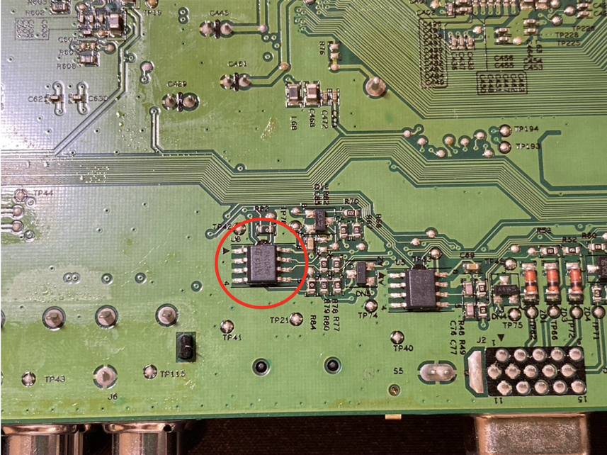
It turns out that the display has multiple chips used for data storage. Each cable interface has its own EEPROM chip (24C02RP) containing a different version of EDID. The firmware is stored on a single flash (25L1605D). The chip containing the HDMI EDID is shown below, labeled U8:
There are a lot of ways to program EEPROM chips, you could use an Arduino if you have one, or there are very affordable programmers on ebay or amazon. I used a CH341A USB flasher with a chip clip:
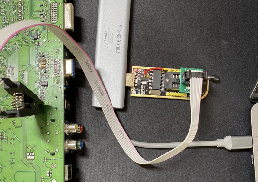
Depending of which EEPROM chip you are using you may need to use a voltage adapter for the CH341A flasher. By default, signal is at 5V which may be too high for some chips. My flasher has a voltage mod that drops voltage from 5V to 3.3V even though is not needed in this instance because 24C02RP chips have a range of 1.8V to 5.5V. Some chips may only operate at low voltages such as 1.8 and connecting high voltage could destroy it permanently.
Read EDID
Now with the clip connected to the chip and the programmer connected through USB to my laptop, I used a Windows VM for the flashing part. These CH341A chips are well supported on Windows and didn’t want to thinker with drivers, so a VM was the fastest solution.
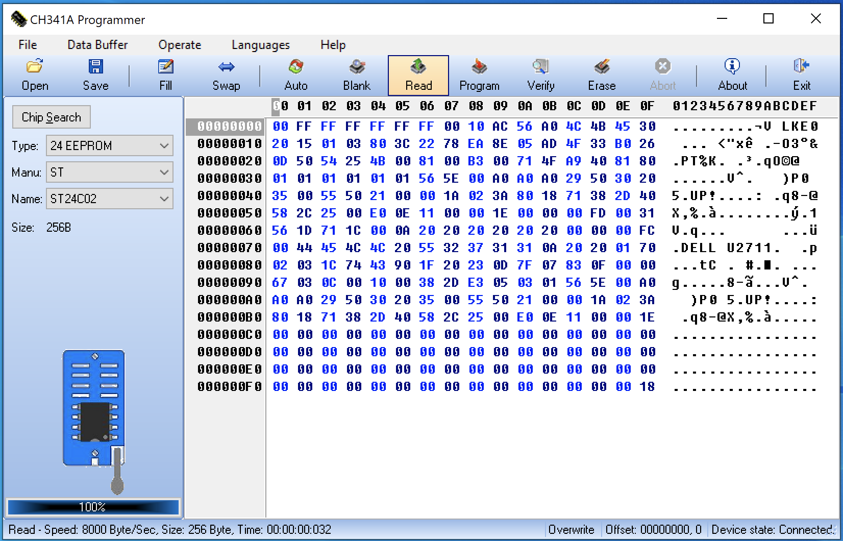
For software, I used the aptly named CH341A Programmer but there are lots of software that support CH341A such as AsProgrammer. First, we need to select the correct chip type before we do any operations, and then we can confirm that everything is working with a read command.
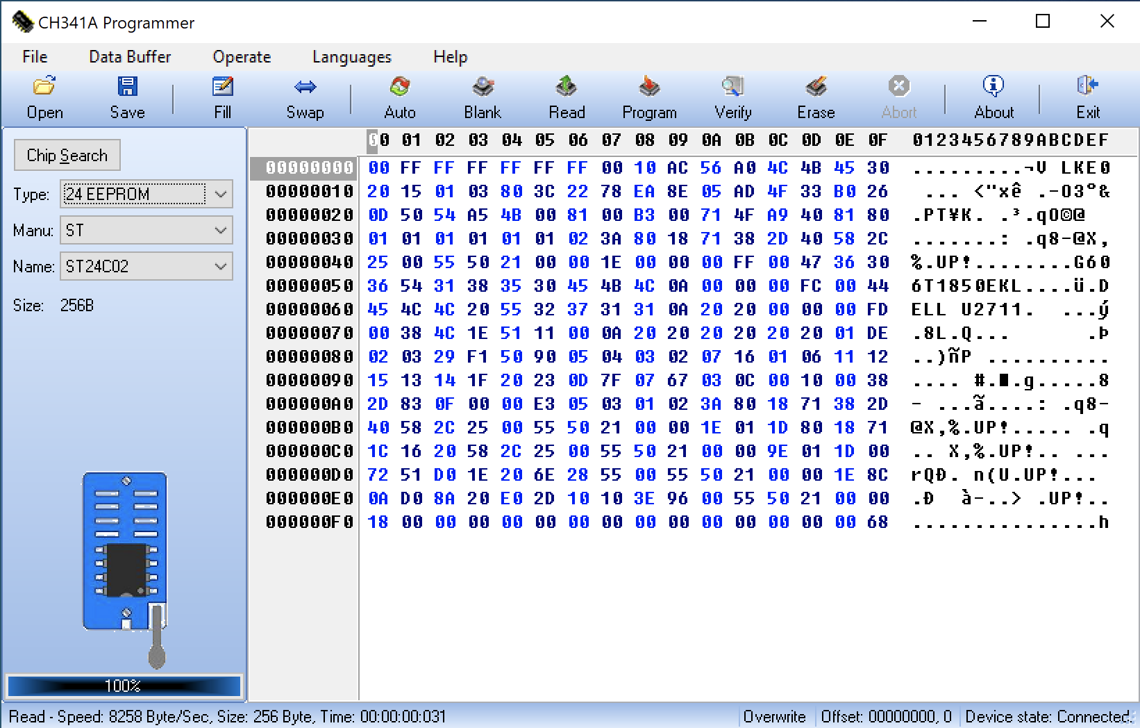
If everything works correctly, the read command should be very fast as the chip contains only 256 bytes of data. Now we can save the data to a file and start working on the modifications we want.
This was the first time I had worked on EDID. I’ve tried a few EDID readers before I settled on EEditGold, but is only available for Windows. Once we feed the data we dumped from the chip to EEditGold, we should see something similar to the below:
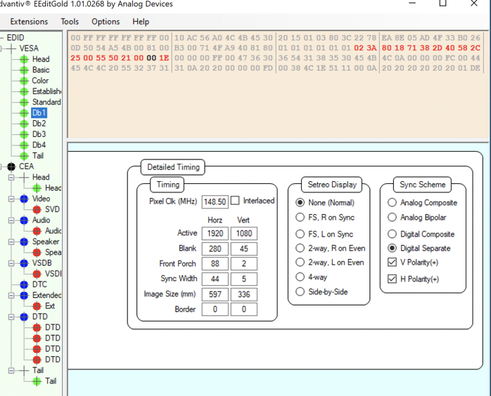
There are a lot of configuration that can be included in the EDID data but what we care about are the Db entries in the VESA section and the DTD entries in the CEA section. Those entries contain the resolution configurations. As you can see in the image above, there are a lot more specifications that we need to worry about other than resolution such as pixel clock and polarity. There are various ways to calculate these but the better option is to just copy these from the DisplayPort EDID or any other display interface EDID that supports our desired resolution.
Here you can see the side by side changes that I did to my EDID:
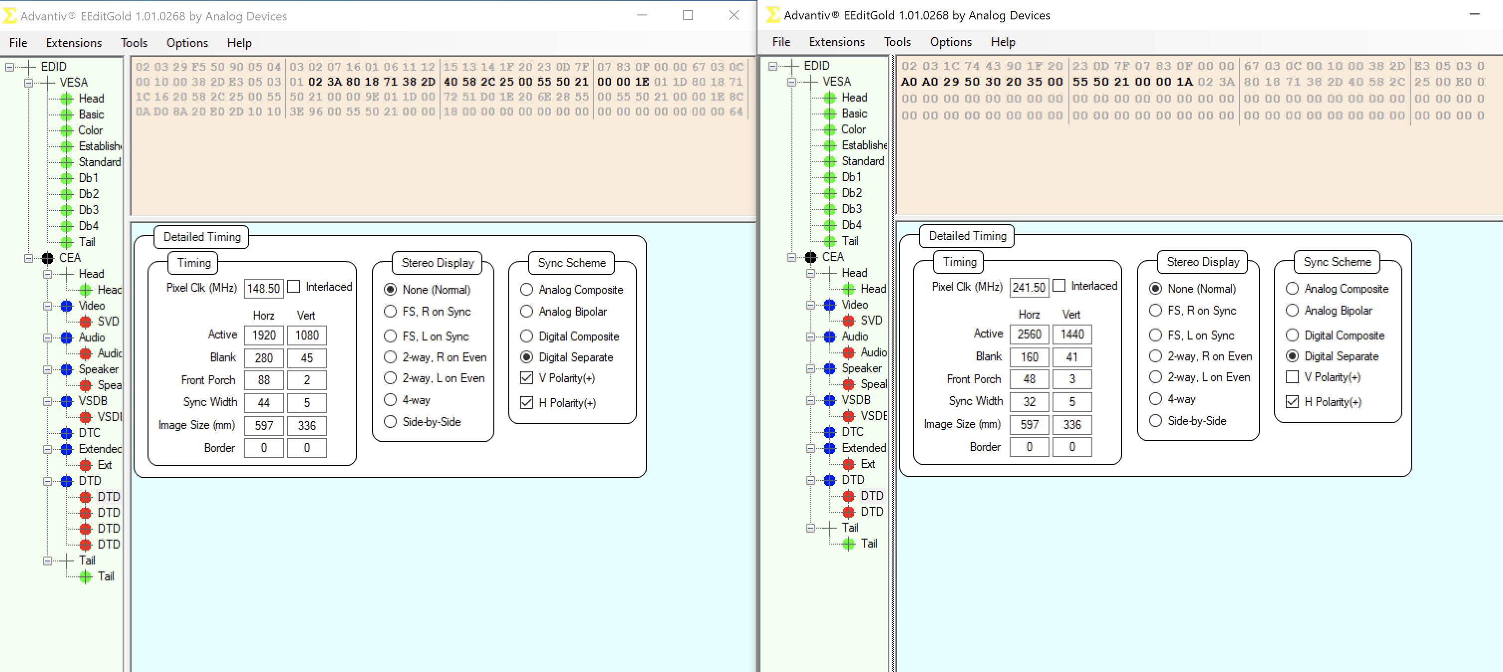
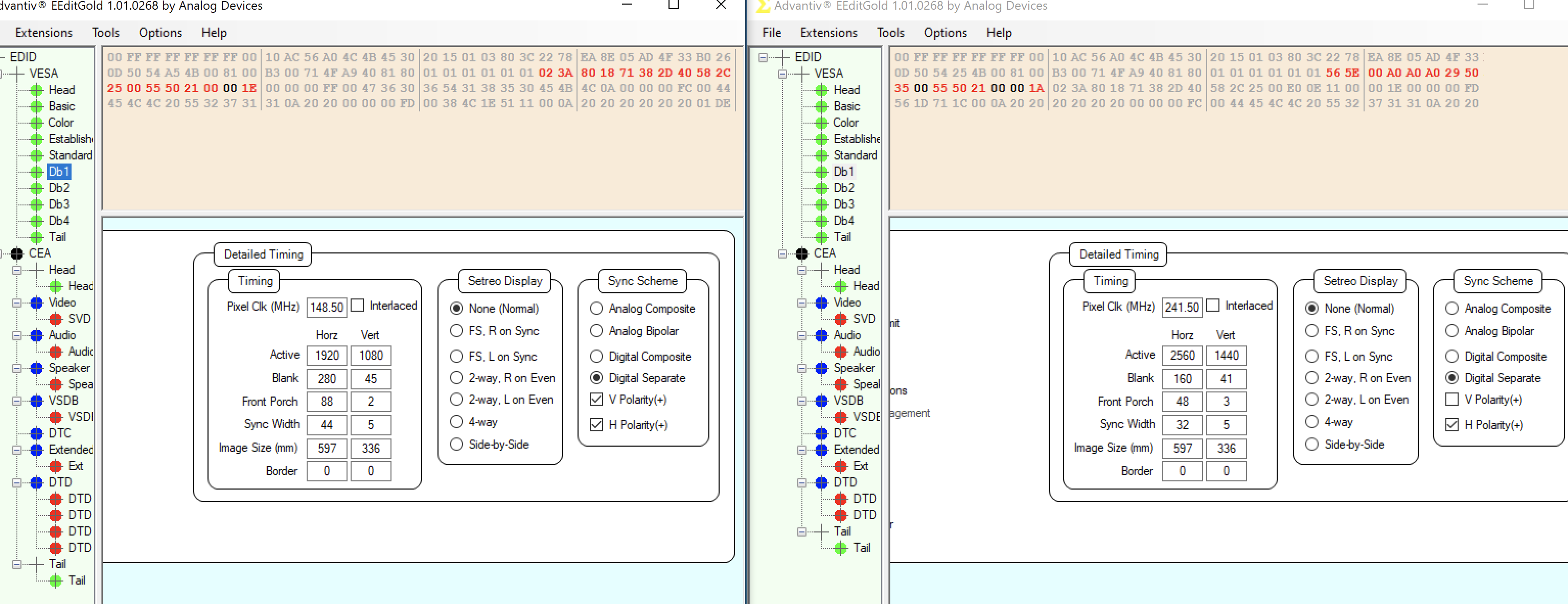
If you run out of space for your added modifications you can delete the entries that you don’t need. You can see in the images above that I deleted some DTD entries.
Conclusion
Now all is left is to save our modification and flash the EEPROM with the new EDID data. We can do this the same way we did the read command but now we open the new file from EEditGold in CH341A Programmer and perform a program command. We can also verify the write operation or can perform another read command and verify manually.
And now for the moment of truth, we reassemble everything the way it was and we hope we didn’t break anything. Our mod worked!
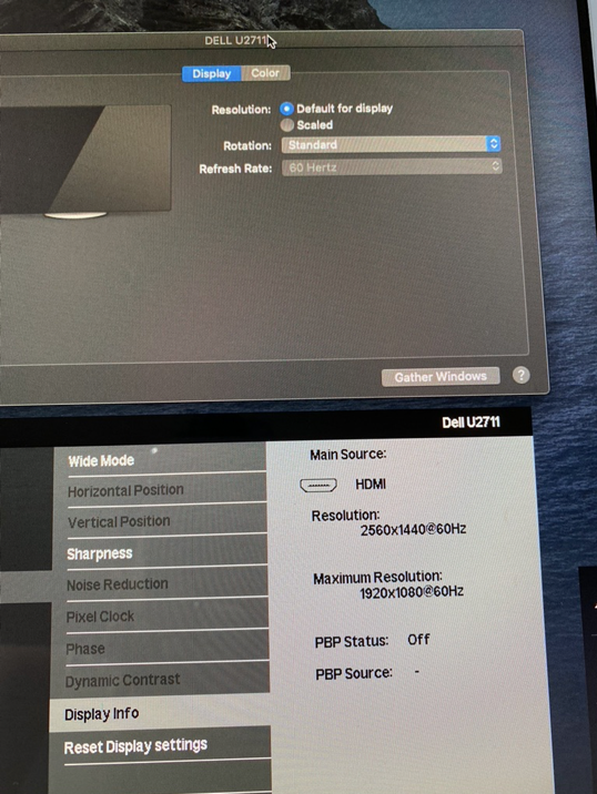
YAY! You can see our changes are working! macOS thinks the 1440p resolution is the default for the display and the display is taking 1440p input over HDMI even though the firmware reports that the supported resolution is only 1080p.